Building fires are not hot enough to melt steel, but are often able to weaken it sufficiently to cause structural failure. For this reason, building codes generally limit the use of exposed steel framing to buildings of one to five stories, where escape in case of fire is rapid. For taller buildings, it is necessary to protect the steel frame from heat long enough for the building to be fully evacuated and the fire extinguished or allowed to burn out on its own. Fireproofing of steel framing was originally done by encasing steel beams and columns in brick masonry or poured concrete. But, this added, in turn, the weight and cost of the frame. The search for lighter-weight fireproofing led first to thin enclosures of metal lath and plaster around the steel members.
Methods for fireproofing steel columns :
a) Encasement in reinforced concrete
b) Enclosure in metal lath and plaster
c) Enclosure in multiple layer of gypsum board
d) Spray-on fireproofing (spray-applied fire-resistive materials (SFRM))
e) Loose insulating fill inside a sheet metal enclosure
f) Water-filled box column made of a wide-flange shape with added steel plates
Methods for fireproofing steel beams and girders :
a) Encasement in reinforced concrete
b) Enclosure in metal lath and plaster
c) Rigid slab fireproofing
d) Spray on fireproofing
e) Suspended plaster ceiling
Wednesday 4 January 2012
Monday 2 January 2012
THE CONSTRUCTION PROCESS OF STEEL STRUCTURES
A steel building frame begins as a rough sketch on the drafting board of an architect or engineer. As the building design process progresses, the sketch evolves through many stages of drawings and calculations to become a finished set of structural drawings. These show accurate column locations, the shapes and sizes of all the members of the frame, and all the loads of the members, but they do not give the exact length to which each member must be cut to mate with the members of its joins, and they do not give details of the more routine connections of the frame. These are left to be worked out by a subsequent recipient of the drawings, the fabricator.
The Fabricator
The fabricator's job is to deliver to the construction site steel components that are ready to be assembled without further processing. This work begins with the preparation in the fabricator's shop of detailed drawings that show exactly how each piece will be made and what its precise dimensions will be. The fabricator designs connections to transmit the loads indicated by the engineer's drawings. Within the limits of accepted engineering practice, the fabricator is free to design the connections to be made as economically as possible, using various combinations of welding and bolting that best suit available equipment and expertise. Drawings are also prepared by the fabricator to show the general contractor exactly where and how to install foundation anchor bolts to connect to the columns of the building and to guide the erector in assembling the steel frame on the building site.
When completed, the fabricator's shop drawings are submitted to the engineer and the architect for review and approval to be sure that they conform exactly to the intentions of the design team. Meanwhile, the fabricator places an order with a producer of steel for the stock from which the structural steel members will be fabricated. When the approved shop drawings, with corrections and comments, are returned to the fabricator by design team, revisions are made as necessary, and full size templates of cardboard or wood are prepared as required to assist the shop workers in laying out the various connections on actual pieces of steel.
The Erector
Where the fabricator's job ends, the erector's job begins. The erector is responsible for assembling into a frame on the building site the steel components furnished by the fabricator. The erector's workers, by tradition, are called iron-workers.
Erecting the First Tier
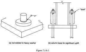
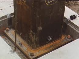
Erection of multistory steel building frame starts with assembly of the first two-story tier of framing. Lifting of the steel components is begun with a truck-mounted or crawler-mounted mobile crane. in accordance with the erection drawings prepared by the fabricator, the columns for the first tier, usually furnished in sections two stories high, are picked up from organized piles on the site and lowered carefully over the anchor bolts and onto the foundation, where the iron-workers bolt them down. Foundation details for steel columns vary. Steel baseplates, which distribute the concentrated loads of the steel columns across a larger area of the concrete foundation, are shop welded to all but the largest columns. The foundations and anchor bolts were put in place previously by the general contractor, following the plan prepared by the fabricator. The contractor may, if requested, provide thin steel leveling plates that are set perfectly level at the proper height on a bed of grout atop each concrete foundation. The baseplates of the column rests upon the leveling plate and is held down with the protruding anchor bolts. Alternatively, especially for larger baseplates with four anchor bolts, the leveling plate is omitted. The column is supported at a proper elevation on stacks of steel shims inserted between the baseplate and the foundation, or on leveling nuts placed beneath the baseplate on the anchor bolts. After the first tier of framing is plumbed up as described below, the baseplates are grouted and the anchor bolts tightened. For the large, heavy columns, baseplates are shipped independently of the columns. Each is leveled in place with shims, wedges or shop-attached leveling screws, then grouted prior to column placement. After the first tier of columns has been erected, the beams and girders for the first two stories are bolted in place. First, positions the components and inserts enough bolts to hold them together temporarily. a gang of bolters follows behind, inserting bolts in all holes and partially tightening them. The two-story tier of framing is then plumbed up with diagonal cables and turnbuckles while checking the alignment with plumb bobs, transits, or laser levels. When the tier is plumb, connections are tightened, baseplates are grouted if necessary, welds are made, and permanent diagonal braces, if called for, are rigidly attached. Ironworkers scramble back and forth, up and down on the columns and beams, protected from falling by safety harnesses that are connected to steel cable lifelines.
Erecting the Upper Tiers
Erection of the second tier proceeds much like that of the first. Two-story column section are hoisted into position and connected by splice plates to the first tier of columns. The beams and columns for the two floors are set, the tier is plumbed and tightened up, and another layer of planks, decking, or safety netting is installed. If the building is not too tall, the mobile crane will do the lifting for the entire building. For a taller building, the mobile crane does the work until it gets to the maximum height to which it can lift a tower crane. The tower crane builds itself an independent tower as the building rises, either alongside the building or within an elevator shaft or a vertical space temporarily left open in the frame. As each piece of steel is lowered towards its final position in the frame, it is guided by an ironworker who holds a rope called a tagline, the other end of which is attached to the piece. Other ironworkers in the raising gang guide the piece by hand as soon as they can reach it, until its bolt holes align with those in the mating pieces. Sometimes, crowbars or hammers must be used to pry, wedge, or drive components until they fit properly, and bolt holes may, on occasion, have to be reamed larger to admit bolts through slightly misaligned pieces. When an approximate alignment has been achieved, tapered steel drift pins from the ironworker's tool belt are shoved into enough bolt holes to hold the pieces together until a few bolts can be inserted. The bolters follow behind the raising gang, filling the remaining holes with bolts from leather carrying baskets and tightening them first with hand wrenches and then with impact wrenches. Field-welded connections are initially held in alignment with bolts, then welded when the frame is plumb. The last beam is placed at the top of the building with a degree of ceremony appropriate to the magnitude of the building. At the very least, a small evergreen tree, a national flag or both are attached to the beam it is lifted.
THE CONNECTIONS OF STEEL STRUCTURES
There are several types of connections in steel structures such as column to base, column to beam, and etc.
As explained in types of joints before, this connections is depend on various necessity.
Column to base plate

Beam to column
 |
| Column to beam connection |
 |
| various component of connector used in jointing a steel structures |
Sunday 1 January 2012
JOINT IN STEEL STRUCTURES
The two most common methods used for connecting steel members in structural steel frames are bolting and welding. Experience has shown that welded connections are usually less expensive when done in the shop under controlled conditions, and bolted connections are usually better suited to field conditions. In most structural steel buildings, welds and bolts are used in combinations to produce the most practical and economical connections possible.
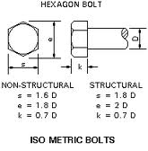
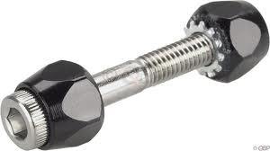
Bolts
Bolts are used more than any other type of connectors. They are easy to use and, in contrast to all other types of connectors, require little special equipment. The development of higher strength steel sand improved manufacturing processes have resulted in the production of bolts that will produce strong structural steel connections. Specifications for most bolted structural joints call for the use of high-strength steel bolts tightened to a hightension. The bolts are used in holes slightly larger than the nominal bolt size. Joints that are required to resist shear between connected parts are designated as either friction-type or bearing-type connectors. Bolted parts should fit solidly together when they are assembled and should NOT be separated by gaskets or any other type of compressible material. Holes should be a nominal diameter, not more that 1/16 inch in excess of the nominal bolt diameter. When the bolted parts are assembled, all joint surfaces should be free of scale, burrs, dirt, and other foreign material. Contact surfaces with friction-type joints must be free of oil, paint, or other coatings.

Welds
Welding is a highly specialized skill, and welding of load-bearing parts of a structure should be performed only by properly qualified personnel. As an EA, you will not be expected to perform welding operations. However, you should have a general knowledge of the principal welding processes and the different types of welds and their applications, and you should know how welding symbols are used to identify welded connections shown in working drawings. The two principal welding processes used instructural work are electric arc welding and oxy-MAPP gas welding. In the electric arc welding process, welding heat, sufficient to fuse the metal together, is developed by an electric arc formed between a suitable electrode(welding rod) and the base metal (the metal of the parts being welded). In the oxy-MAPP gas welding process, heat is obtained by burning a mixture of MAPP gas and oxygen as it is discharged from a torch designed for this purpose. While electric arc welding is normally used for metals that are 1/8 inch or larger in thickness, oxy-MAPP gas welding is usually restricted to thinner metals.
Bolts
Bolts are used more than any other type of connectors. They are easy to use and, in contrast to all other types of connectors, require little special equipment. The development of higher strength steel sand improved manufacturing processes have resulted in the production of bolts that will produce strong structural steel connections. Specifications for most bolted structural joints call for the use of high-strength steel bolts tightened to a hightension. The bolts are used in holes slightly larger than the nominal bolt size. Joints that are required to resist shear between connected parts are designated as either friction-type or bearing-type connectors. Bolted parts should fit solidly together when they are assembled and should NOT be separated by gaskets or any other type of compressible material. Holes should be a nominal diameter, not more that 1/16 inch in excess of the nominal bolt diameter. When the bolted parts are assembled, all joint surfaces should be free of scale, burrs, dirt, and other foreign material. Contact surfaces with friction-type joints must be free of oil, paint, or other coatings.
Welds
Welding is a highly specialized skill, and welding of load-bearing parts of a structure should be performed only by properly qualified personnel. As an EA, you will not be expected to perform welding operations. However, you should have a general knowledge of the principal welding processes and the different types of welds and their applications, and you should know how welding symbols are used to identify welded connections shown in working drawings. The two principal welding processes used instructural work are electric arc welding and oxy-MAPP gas welding. In the electric arc welding process, welding heat, sufficient to fuse the metal together, is developed by an electric arc formed between a suitable electrode(welding rod) and the base metal (the metal of the parts being welded). In the oxy-MAPP gas welding process, heat is obtained by burning a mixture of MAPP gas and oxygen as it is discharged from a torch designed for this purpose. While electric arc welding is normally used for metals that are 1/8 inch or larger in thickness, oxy-MAPP gas welding is usually restricted to thinner metals.
 |
| Types of weld |
 |
| Welded Joints |
Saturday 31 December 2011
THE COMPONENTS OF STEEL STRUCTURE
There are several components of steel structure which can be divided in two general types ; Main Frame & Connectors.
Main Frame ==> Beams, columns, girders, hollow section structural, bar, etc.

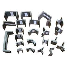
Connectors ==> Structural tee, angle, channel, plates, etc.
Structural Tee
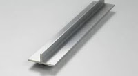

Usually used as a connectors..but also can be used as tee beam or floor.
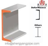
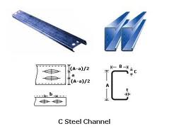
Channel (C-Shape)
Main Frame ==> Beams, columns, girders, hollow section structural, bar, etc.
 |
| American Standard I-Beam(also known as S-Shape) |
| Designation | Depth | Width | Thickness Web | Thickness Flange | Sectional Area | Weight | Moment of Inertia - Ix | Moment of Inertia - Iy | Section of Modulus - Wx | Section of Modulus - Wy | |
|---|---|---|---|---|---|---|---|---|---|---|---|
| in | in | in | in | in**2 | lb/ft | in**4 | in**4 | in**3 | in**3 | ||
| insert! | S24 x 121 | 24.5 | 8.050 | 0.800 | 1.090 | 35.6 | 121 | 3160 | 83.3 | 258 | 20.7 |
| insert! | S24 x 106 | 24.5 | 7.780 | 0.620 | 1.090 | 31.2 | 106 | 2940 | 77.1 | 240 | 19.6 |
| insert! | S24 x 100 | 24 | 7.425 | 0.745 | 0.870 | 29.3 | 100 | 2390 | 47.7 | 199 | 13.2 |
| insert! | S24 x 90 | 24 | 7.125 | 0.625 | 0.870 | 26.5 | 90 | 2250 | 44.9 | 187 | 12.6 |
| insert! | S24 x 80 | 24 | 7.000 | 0.500 | 0.870 | 23.5 | 80 | 2100 | 42.2 | 175 | 12.1 |
| insert! | S20 x 96 | 20.3 | 7.200 | 0.800 | 0..920 | 28.2 | 96 | 1670 | 50.2 | 165 | 13.9 |
 |
| Wide Flange Beam(also known as W-Shape) |

Connectors ==> Structural tee, angle, channel, plates, etc.
Structural Tee

Usually used as a connectors..but also can be used as tee beam or floor.
Channel (C-Shape)
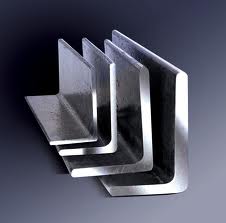
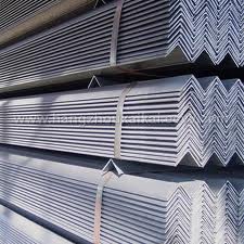
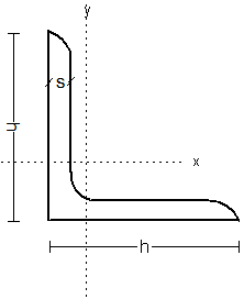
Angle (L-Shape)
Tuesday 27 December 2011
TOPIC 1 : STEEL STRUCTURE
INTRODUCTION
Steel, strong and stiffs, is a material of slender towers and soaring spans. Precise and predictable, light in proportion to its strength, it is also well suited to rapid construction, highly repetitive building frames, and architectural details that satisfy the eye with a clean, precise elegance. Among the metals, it is uniquely plentiful and inexpensive. If its weakness - a tendency to corrode in certain environments and a loss of strength during severe building fires - are held in check by intelligent construction measures, it offers the designer possibilities that exist with no other material.

Steel, strong and stiffs, is a material of slender towers and soaring spans. Precise and predictable, light in proportion to its strength, it is also well suited to rapid construction, highly repetitive building frames, and architectural details that satisfy the eye with a clean, precise elegance. Among the metals, it is uniquely plentiful and inexpensive. If its weakness - a tendency to corrode in certain environments and a loss of strength during severe building fires - are held in check by intelligent construction measures, it offers the designer possibilities that exist with no other material.

INTRODUCTION TO CQ 302
SYNOPSIS
CONSTRUCTION TECHNOLOGY 3 course exposes students to the technology
involved in the construction. The course emphasizes is on the steel structure, long
span roof, external works, basement and advance building structure. This course also
gives students knowledge on renovation works.
1.0 STEEL STRUCTURE (04 :00)
This topic elaborates on the component of steel structure,
types of joint, Uniform Building By-laws clauses related to
protection of corrosion and fire, selection factors related to
cost, time and quality.
2.0 LONG SPAN ROOF (06 : 00)
This topic explains the construction of lattice roof, portal
frame roof, shell roof and finishes, natural lighting and
ventilation of long span roof.
3.0 BASEMENT (04 : 00)
This topic covers the construction of basement, methods of
excavation and relevant clauses in Uniform Building By-
Laws.
4.0 EXTERNAL WORKS (06 :00)
This topic covers the construction of external works that are
site clearance and earthwork, drainage, landscape,
roadwork, road furniture, retaining wall, fencing and gate.
5.0 INDUSTRIALISED BUILDING SYSTEM AND GREEN
TECHNOLOGY (04 :00)
This topic covers the Industrialized Building System (IBS)
and green technology to develop sustainable buildings in
the construction industry.
6.0 RENOVATION WORKS (06 : 00)
This topic explains the renovation works, underpinning
works and safety factors in execution of the works.
Subscribe to:
Posts (Atom)